

Basic Circuit Theory
This is a brief introduces the concept of voltage, current and power and the circuit components of resistance, capacitance and inductance.
Voltage, Current and Resistance
Figure 1 shows a voltage source (V) connected to a resistance (R). When the two terminals of a voltage source (such as a battery) are connected across a resistance, a current (I) flows from the positive terminal of the voltage source, through the resistance and back to the negative terminal of the source. The direction of the current is indicated by the arrows on the wires connecting the voltage source and resistance. Voltage is measured in units of volts (V), and current is measured in units of amperes, or amps (A).
The ability of a material to conduct electricity depends on the freedom of electrons in the material to move. A good conductor, such as copper, has many more electrons able to move freely than a poor conductor, such as glass. The conductance of a material is a measure of its ability to carry current. In practice, the resistance of a material to the flow of electrons, which is the inverse of conductance, is more commonly quoted. Resistance is measured in ohms ().
The voltage across a circuit, the current flowing through it, and the resistance of the circuit are related by Ohm’s Law:
For example, if a current of 100 mA flows through a resistance of 50 , the voltage across this resistance must be 5 V.
Power
When a current passes through a resistance, heat is generated. This heating is caused by the dissipation of energy in the resistance. Power (P) is the rate at which energy is dissipated, which is measured in watts (W). The power dissipated in a resistance, R, is given by:
Since Ohm’s law tells us that V=IR, the equation can also be written:
Direct and Alternating Current
The term direct current (DC) is used to describe the constant current supplied by a source such as a battery, such as the battery in Figure 1. This constant current is shown in Figure 2(a). Ohm’s law tells us that a constant voltage across a constant resistance must always lead to a constant current.
If the voltage generated by the voltage source varies over time and the resistance remains constant, the current must vary in proportion to the voltage. The term alternating current is used to describe a current that varies sinusoidally, as shown in Figure 2(b).
A circuit containing an alternating voltage source is shown in Figure 3. The relationship between the time-varying voltage and the time-varying current is described by Ohm’s law:

Figure 1. Voltage (V), current (I) and resistance (R).

Figure 2. (a) Direct and (b) alternating current.
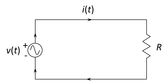
Figure 3. Voltage, current and resistance for an alternating voltage source.
Frequency and Angular Frequency
For a sinusoidal voltage,
where
is the frequency in hertz and
is the angular frequency in radians per second.
Average and RMS Voltage and Current
When an alternating current flows, the average current is zero, as illustrated in Figure 4(a). This means that the average voltage is zero.
Yet the alternating voltage and current do cause heating of a resistance. A current, Irms, (called the root-mean-square current, or RMS current) is defined as the DC current that has the same effect as the AC current i(t). It can be shown that for a sine wave:
and
For AC currents, the power dissipated in a resistance is calculated in terms of the root-mean-square values. That is:
or
For a sine wave, this equation can be written:
or
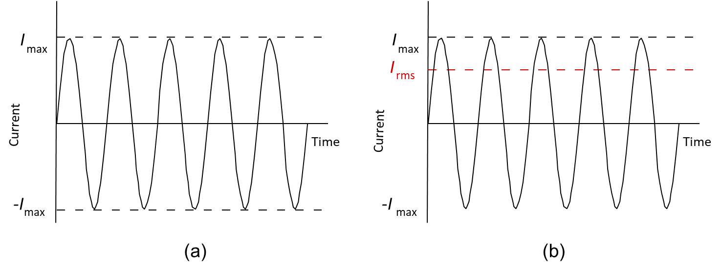
Figure 4. Maximum and RMS current.
Circuit Components
Figure 5 shows the symbols for the circuit components of resistance, capacitance and inductance.
We have already met resistance as a measure of the reluctance of a material to support electron flow. All circuits have some resistance since no real components have electrons that are perfectly free to move.
The capacitor is obtained by placing two conducting plates near to each other, separated by a non-conducting material called a dielectric. The capacitance, C, of the capacitor is measured in farads (F). A voltage across the plates results in an electric field between them and the current that flows is directly proportional to the time rate of change of the voltage across the plates. In steady state, a capacitor therefore acts as an open circuit to DC.
A current passing through a wire produces a magnetic field around the wire. Winding the conductor into a coil strengthens the magnetic field. The resulting element is called an inductor, whose inductance (L) is measured in henry (H). The voltage across an inductor is directly proportional to the time rate of change of the current through it. In steady state, an inductor therefore acts as a short circuit to DC.

Figure 5. Symbols for resistance, capacitance and inductance.
IMPEDANCE
In AC circuits, resistance generalizes to impedance (Z), which represents opposition to current in the presence of capacitance and inductance. Impedance depends on frequency and may include both resistive and reactive (capacitive and inductive) components. The resistive component dissipates energy and results in attenuation of signals. The reactive component stores and releases energy, introducing phase shifts that vary with frequency. When different frequency components experience unequal phase shifts or amplitudes, signal distortion can occur. In transmission media, attenuation can often be compensated by amplification, whereas distortion requires equalization or other corrective measures.
Signal-to-Noise Ratio
In communications, we are not just interested in the strength of a signal, but we are also interested in the noise that is present. For example, a strong signal in the presence of strong noise may not be much more useful than a weak signal in the presence of weak noise. We are therefore interested in maximizing the signal while minimizing the noise. The measure most commonly used to describe this is the signal-to-noise ratio (SNR):
where S is the signal power and N is the noise power.
In decibels (see Appendix C), the SNR is:
In most communications systems, noise is modeled as random Gaussian noise, and SNR is calculated using average signal and noise powers measured over a specified bandwidth.
edVirtus Communications Courses
You may be interested in the following edVirtus communications courses:
One-day Satellite Communications—Overview.
Three-day Satellite Communications—Intermediate.
Five-day Satellite Communications—Advanced.